|
Drawings in ABACUS are more than just arbitrary representations. They are customised views of the architecture, formatted and arranged to show particular meaning.
The Drawing Tool enforces the hierarchical structure of the architecture, so that components are visually nested within other components - effectively giving a 'plan view' of the elements. Once a component or a connection has been defined in the architecture, it can be used in any number of different diagrams. Importantly, the Drawing Tool is closely linked to the architectural model, so that changes done in either one are always reflected in the other.
The tool works by associating shapes with particular connection and component types defined in the Types section of the architecture. These associations vary depending on the type of diagram being drawn, and it is possible that one type of component (or connection) may have different representations in the different diagrams, depending on the context.
To set up an association between a shape and a component or connection type
1.Ensure that you have a new or existing diagram open.
2.Maximise the ABACUS application, and configure the window proportions as you desire.
3.Select the Shapes tab or the Connectors tab in the stencil window.
4.In the Type branch of the Explorer, locate the component or connection type you would like to associate with a shape or connector.
5.Select the chosen type element from the tree, drag it over to the Shapes tab or Connectors tab, and drop it onto the shape or connector you would like to use.
 Note Note
You can verify an association you have created by selecting the Components or Connections tab in the Stencil window, which show the currently associated elements.
To add new shapes to your diagrams/library
1.Create a MS Visio diagram with the shapes that you want to add to your diagram and import the MS Visio diagram.
 Tip Tip
It is important what size you make the master shape in MS Visio because the ABACUS canvas is sized in pixels and only Millimetres units in MS Visio convert granularly to pixels on a 4 pixels to 1 Millimetre ratio. Furthermore, the default ABACUS shapes are typically 60 pixels high so that translates to 15 Millimetres in MS Visio. Meaning an advisable master shape size in MS Visio is 25mm wide by 15mm high as this will translate to 100 pixels wide by 60 pixels high in ABACUS.
Tip
If you want to have a little 'icon' in the top left-hand corner of a shape then you can simply create the 'icon' in the master MS Visio shape using the MS Visio Drawing Tool palette (note that only simple lines, circles and rectangles are supported and rasterise/bitmap shapes in particular are not supported). Furthermore, if you want the icon to be fixed in size/scale within the shape in ABACUS then you can group the 'icon' in the master MS Visio shape by selecting all its elements, right-clicking one element, selecting Shape | Group, then right-clicking the grouped shape and selecting Data | Shape Data..., selecting Yes in the dialog that appears and then adding a property with the Label set to LockScale (note the upper-case 'L' and 'S'), the Type set to Boolean and the Value set to be TRUE (note it is all in upper-case).
Tip
If you want to have a portion of the shape frozen from scaling horizontally or vertically (as is typical with a 'swim-lane' shape) then you can right-click the portion(s) of the master MS Visio shape that you want frozen from scaling and select Data | Shape Data..., selecting Yes in the dialog that appears and then adding a property with the Label set to LockXScale or LockYScale (note the upper-case 'L' and 'S'), the Type set to Boolean and the Value set to be TRUE (note it is all in upper-case), for locked horizontal or vertical scaling respectively.
Tip
To allow the colouring of the shape in ABACUS after importing rather than the shape always being a fixed colour it is advisable to make the master MS Visio shape's fill transparent and then use the inbuilt ability in ABACUS to colour a shape's background. This only works with rectangle or near-rectangle (e.g. rounded rectangle) shapes as the entire rectangular background will be coloured.
2.Open the corresponding diagram and select the Components tab in the stencil window.
3.For each new shape that you want to make available to other diagrams Right-click the shape and select Add to Shapes Library. This will make the shape available on the Shapes tab in the stencil window.
4.Associate the relevant component type with the new shape from the Shapes library according to the steps described above.
Note
Only simple and "vector-based" shapes are supported in ABACUS at the moment, i.e. bitmaps are not supported. However, tools such as Vector Magic (www.vectormagic.com) are available that will readily convert bitmap images into vector-based shapes (i.e. SVG format) that can be opened in MS Visio and hence utilised in ABACUS as per the above instructions.
- or -
2.Right-click any freeform shape on your diagram and select Add to Shapes Library.

Adding Components and Connections
The Drawing Tool allows you to add existing components and connections from the repository or create new components and connections as you are drawing a diagram. As components and connections are created in diagrams, they are simultaneously added into the repository. There are three recommended ways of adding components to a diagram and three recommended ways of adding connections to a diagram:
To create a new component or connection on a diagram from the stencil
1.Ensure that you have a new or existing diagram open.
2.Select the Components or Connections tab in the stencil window to see the associated shapes. Only these shapes can be used to create new model elements.
3.Click and drag or Copy and Paste for one of the available associated shapes onto the drawing canvas.
4.Start typing a name for the new element in the dialog and any existing elements that are matched are suggested and can be chosen rather than adding a new element to the architecture.
5.Click OK and the new or existing component or connection will appear on the canvas and in the explorer tree.
6.If a shape was dropped onto an existing component, then it will either become a child of that component (if the shape came from the Components tab), or will be attached to that component (if the shape came from the Connections tab).
Note
It is sometimes necessary to adjust the new component or connection into a different place in the architectural hierarchy using the explorer.
To place an existing component or connection from the repository onto a diagram
1.Ensure that you have a new or existing diagram open.
2.Be sure that you have both the Drawing Tool and Explorer windows viewable.
3.In the Explorer, locate the component or connection (element) you would like to add to the diagram.
4.Click and drag or Ctrl + c/ right-click and select Copy on the chosen element onto the diagram. A shape representing the element will appear on the canvas.
Note
If the type of the chosen element is already associated with a shape, the corresponding shape will appear on the canvas. If, however, there is no defined association for that particular element, a default shape (rectangle) will appear on the canvas unless the Enforce Diagram Viewpoints option is on in which case the shape will not be added to the diagram.
Tip
When a component is placed on a diagram which is connected to another component already on the diagram, the Drawing Tool will query if you would like to show the connection(s) between them. Also, if there are any children of the component the Drawing Tool will query if you would like to include the children, in a recursive manner.
Tip
You can also drag short-cuts and references of components/connections onto the diagram.
To create a connection between 2 components or a connected component on a diagram using dynamic connector
1.Ensure that you have a new or existing diagram open.
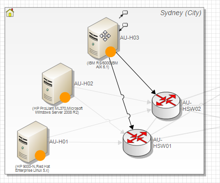
2.Hover over a component on the diagram that you wish to connect to another component and you will notice 2 icons appear outside the top-right of the boundary of the shape as shown below. Note: The top icon is for creating a connection where the hovered component is to be the source, the bottom icon is for creating a connection where the hovered component is to be the sink.
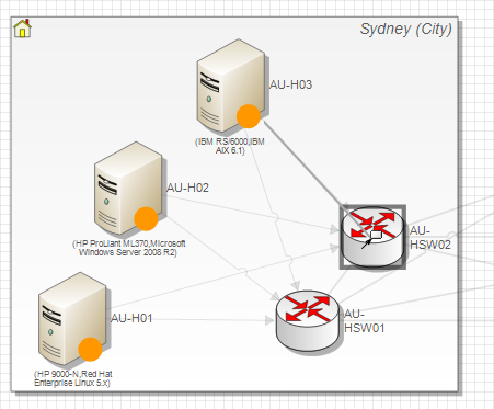
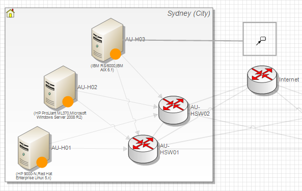
3.Move the cursor over the desired icon and click and drag the icon to over either over another component or free space on the canvas as shown below.
4.To connect to an existing component choose the Attach to... item in the pop-up menu and if required browse to the sub-menu to choose from the available connection types.
- or -
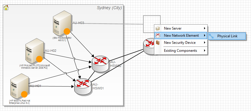
4.To create a connected component chose from the New... items in the pop-up menu and if required browse to the sub-menu to choose from the available connection types as shown below. Start typing a name for the new element in the dialog and any existing elements that are matched are suggested and can be chosen rather than adding a new element to the architecture.
- or -
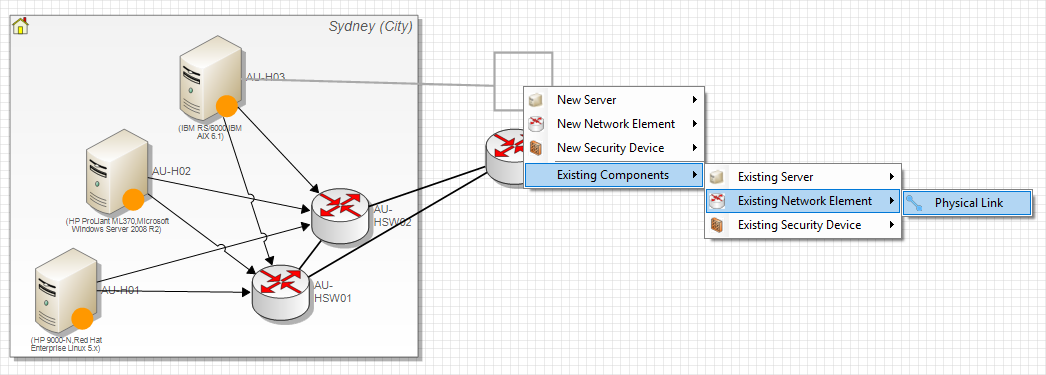
4. To add an existing component/s from the architecture choose from the Existing components... items in the pop-up menu and choose from one of the sub-menu options for the type of existing component you wish to add and select the type of connection that you want to use. You can then select from the dialog which pre-existing components of the selected type you would like to add with the selected connection.
Note
The availability of items in the pop-up menu and sub-menu is governed by the constraints in the metamodel. That is only the valid source or sink component types as determined by connection constraints will be presented as the Attach to... and New... and Existing Components... (to Existing...) menu items.
On top of constraints, only components/connections that are part of the stencil will be shown.
To open the element selection dialog and place existing components or connections from the repository onto a diagram
1.Ensure that you have a new or existing diagram open.
2.Click the Open Element Selection button in the Diagram toolbar or via the context menu by right-clicking an empty area on the diagram. Note: the element selection dialog will open with the last state of any filters saved.
3.Choose any additional content that is desired to be added to the diagram and click OK. Note: the new content will be added to clear space on the canvas and the diagram can be subsequently laid out again via the Layout Diagram sub-menu option in the Diagrams context menu.
Using Freeform Shapes
It is often desirable to create visual elements in a diagram for purely aesthetic reasons. These elements may help improve the layout and appearance of a diagram, yet they do not have a strict architectural significance. The Drawing Tool allows the use of freeform shapes to provide drawing flexibility.
To add a freeform shape to a diagram
1.Ensure that you have a new or existing diagram open.
2.Select the Shapes or Connectors tab in the stencil window.
3.Click and drag one of the available shapes or connectors onto the drawing canvas. The new element will appear on the canvas - but not in the explorer tree.
Note
Freeform shapes are 'non-associated' shapes, as they have no association with any particular component or connection in the architectural model.
To display repository information in freeform shapes on a diagram
1.Ensure that you have a new or existing diagram open.
2.Right-click the freeform shape and select Annotation | Display.
3.Choose to display either the Diagram Name, Diagram Description, Diagram Property, Viewpoint Name or Architecture Name.
Note
The text in the freeform will automatically update as the underlying repository data changes. In this way a diagram 'title block' can be created for, and then easily copied across, diagrams.
Using Floating Shapes
Floating shapes are essentially another way to represent components in a diagram. Consider an organisation with key divisions: CEO, Marketing, Sales and Development.
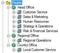
Tree View
These divisions may be visually represented in a layered manner :
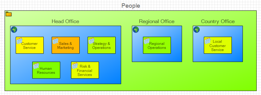
Layered View
Or they may be visually represented in a staggered / floating manner to show hierarchy :
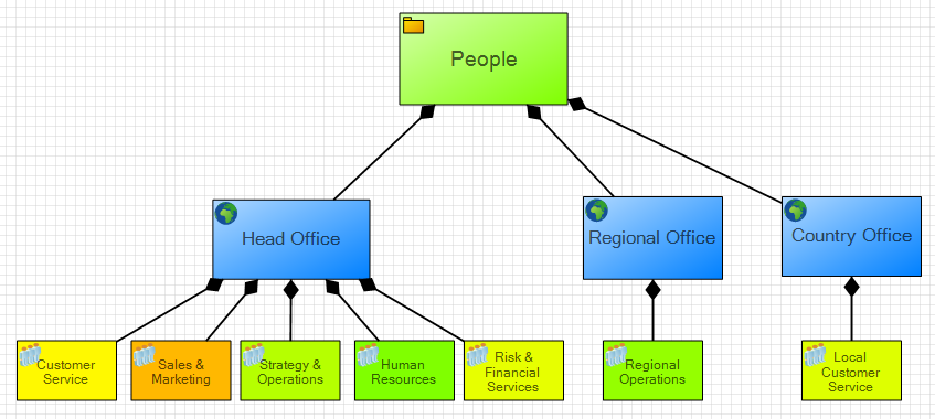
Staggered / Floating View
The latter representation uses the concept of floating shapes.
To convert a layered component shape into a floating shape
1.Ensure that you have a new or existing diagram open.
2.Select the component in your diagram you want to represent as a floating shape or an associated shape in the Components tab of the stencil window you want all instances as floating shapes.
3.Right-click the shape and select Float Component from the context menu that appears. Note the diamond headed connection from the parent component(s) to the floating component(s).
4.Click and drag the component to the desired place. When a floating component is selected it will have a blue outline.
To convert a floating component shape into a layered shape
1.Ensure that you have a new or existing diagram open.
2.Select the component in your diagram that is currently being shown as a floating shape or an associated shape in the Components tab of the stencil window you want all instances as layered shapes.
3.Click and drag the floating component(s) back to the parent(s) (according to the diamond headed connection). Note: If you don't do this then when you convert the component(s) back to being layered the hierarchy of your model might be affected.
4.Right-click the shape and deselect Float Component from the context menu that appears. Note that the diamond headed connection from the parent component(s) to the floating component(s) will disappear.
Replicas
The Drawing Tool allows you to add the same component to a diagram several times with each additional visual instance of the component on the diagram referred to as a replica. This is particular useful for diagrams where a component has a large number of connections attached to it and it is preferable to show the component in multiple locations closer to the origin of each of the connections, or for diagrams where a one-to-many relationship of a component is preferable to show using the floating feature (described above) with the component in multiple locations on top of the 'many' components it is related to.
Note
You can attach / detach connections to / from the original instance of the component on a diagram (as always) but also to any of the replicas, however, when connections are automatically added to a diagram they are attached to the first instance of the component on the diagram by default.
Note
Replicas can be merged with each other by right-click and drag then selecting Merge Replicas, however, merging a replica with a different component will result in any other replicas disappearing from the diagram.
Note
There is no visual difference between the original instance of a component on a diagram and any replicas. Furthermore, the right-click menu for the original component on a diagram and any replicas is identical, with for example Show in Explorer taking you to the same component in the Tree View of the repository (aka the model). However, right-clicking the component in the Tree View of the repository and selecting Go To and browsing to a diagram with replicas will always take you to the 'oldest' instance of the component on the diagram. Typically this will be original instance that was added to the diagram but if that original instance was subsequently deleted or merged with a replica then Go To will jump to the oldest of the remaining replicas that were added.
To add a replica to a diagram
1.Ensure that you have a new or existing diagram open.
2.Right-click an existing component on the diagram and select Create Replica. A replica of the selected component will be created to the right of the original component.
- OR -
Select an existing component on a diagram and press Ctrl + C or right-click an existing component on the diagram and select Copy. Now right-click the location on the diagram that you want the replica and select Paste as Replica. Note: Pressing Ctrl + V (or right-clicking and selecting Paste) will create a copy of the original component NOT a replica.
- OR -
Click and drag a component from the Tree View of the repository (aka the model) onto a diagram where the component already exists.
Configuring Connection Caps / Ends
The Drawing Tool allows you to set the symbol used at the ends of the connection lines either to a fixed symbol or a symbol dependant on a property on the connection itself. This is particularly useful for diagrams where the direction of a connection is required to be shown, or for diagrams where the cardinality of the connection (or the direction) is contained in a property on the connection itself, e.g. 'One-to-Many' vs 'Many-to-Many' (or 'Source to Sink' vs 'Sink to Source').
To configure connection caps / ends on a diagram
1.Ensure that you have a new or existing diagram open.
2.Select the Connections tab in the stencil window.
3.Right-click one of the associated connection types and select Configure Caps....
4.For a fixed connection cap / end at either the source or sink end of the connection make sure the relevant Fixed radio button is selected and then select the connection end symbol from the pull down, e.g. 'Arrow Head' or 'Diamond'.
- OR -
For a property-based connection cap / end at either the source or sink end of the connection make sure the relevant Using Property radio button is selected, then click the '...' button and select the required property and then next to each connection end symbol enter the property values for which the specific connection symbol are to be shown.
Note
Multiple property values for a given connection end symbol may be entered separated by commas. E.g. the dialog below shows that if the 'Data | Cardinality' property has a value of 'One-to-Many' then the source end of the connection will have two line strokes through it and the sink end of the connection will have one line stroke through it and then a fan-out of two line strokes at the end.
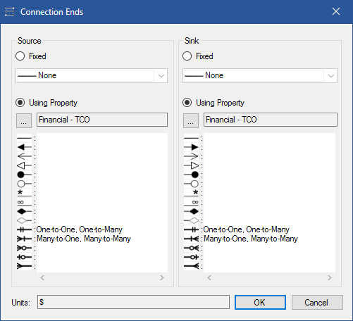
Configure Caps dialog
See Also
The Drawing Tool | Populating your architecture | Analysing your architecture
© 2001-2024 Avolution Pty Ltd, related entities and/or licensors. All rights reserved.
|